3-Axis CNC Machining
Reliable 3-axis milling for plates, blocks, brackets, housings and components with accessible prismatic features.
Discuss a 3-axis partDrawing-based 3-axis, 3+2 positional and simultaneous 5-axis milling for brackets, blocks, plates and housings in industrial equipment. Start with the features that matter to your assembly.
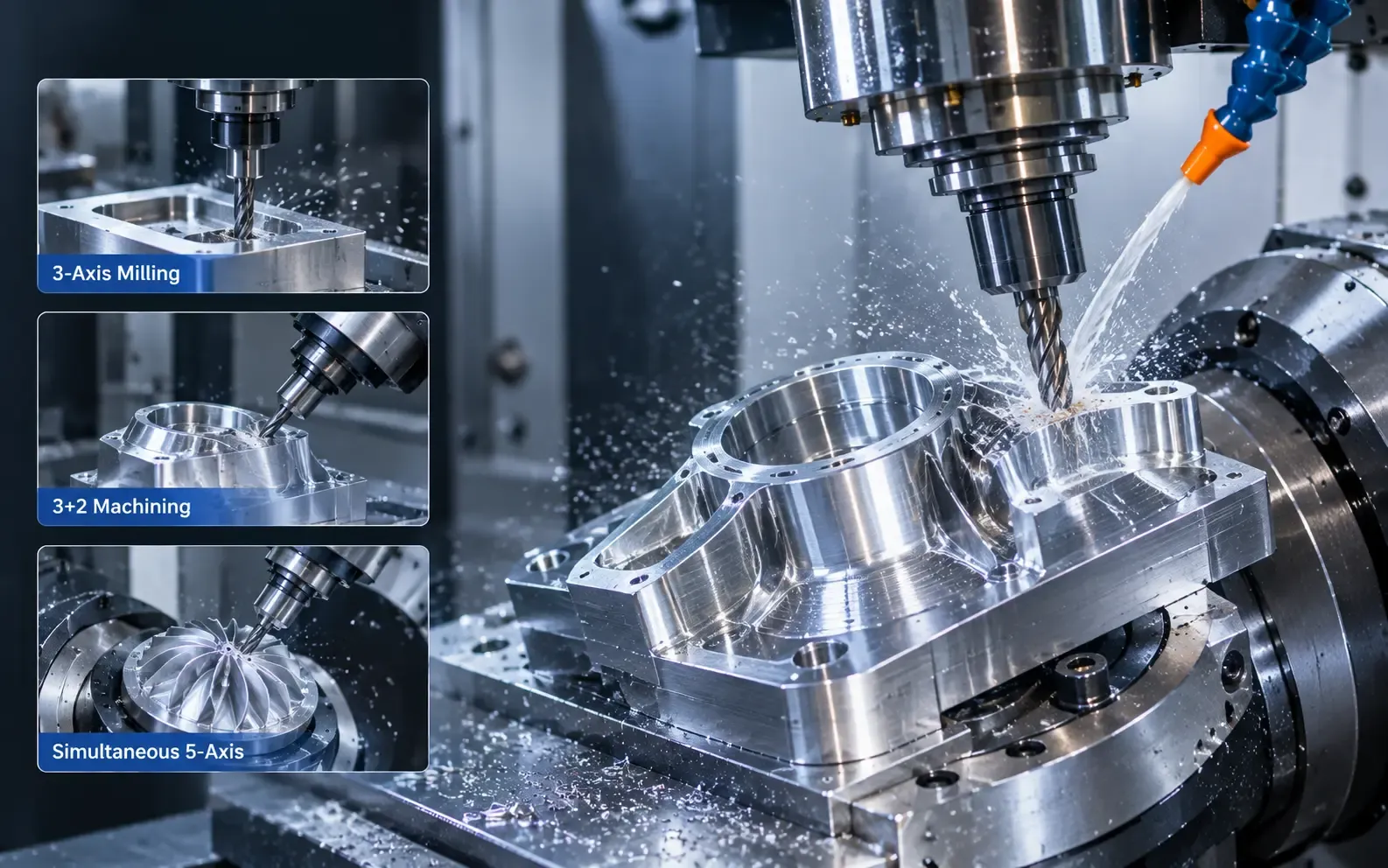
Belaro offers 3-axis, 3+2 positional and simultaneous 5-axis milling, with the process route reviewed against the drawing, material, tolerances and critical features.
Reliable 3-axis milling for plates, blocks, brackets, housings and components with accessible prismatic features.
Discuss a 3-axis partAlso called positional 5-axis milling: two rotary axes position the part or tool at a fixed angle, then remain stationary during 3-axis cutting. Suitable for angled holes, inclined faces and pockets on multiple sides, subject to tool access and fixture review.
Discuss a 3+2 partSimultaneous 5-axis machining for complex surfaces, angled features and geometries that benefit from multi-directional tool access.
Discuss a 5-axis partExplore typical milled part families for industrial OEM applications. These representative images describe component types; suitability is assessed against your drawing and actual process capability.
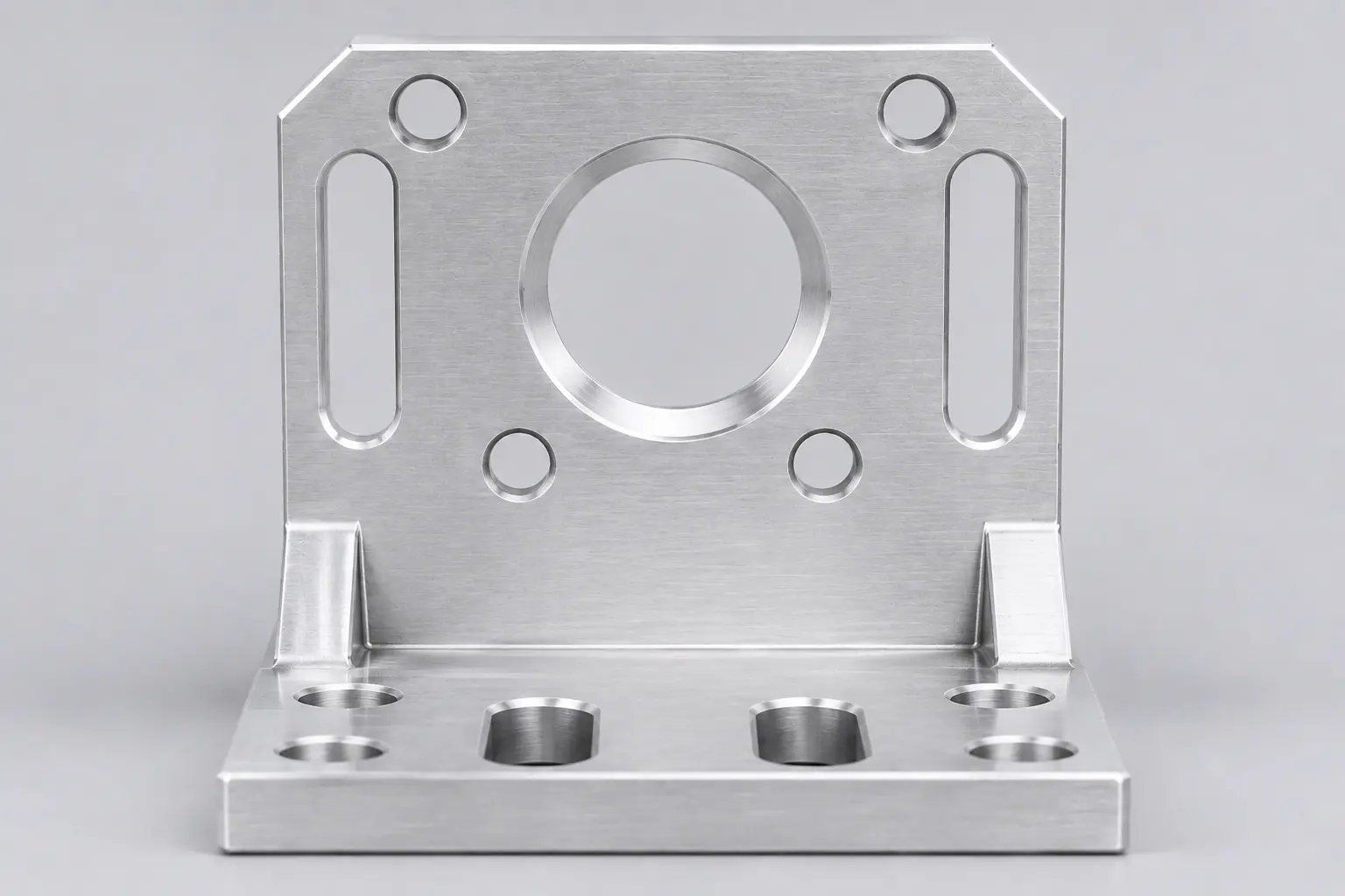 REPRESENTATIVE PART
Custom brackets and supports for mounting sensors, tooling and mechanical assemblies to your equipment.
Explore this part family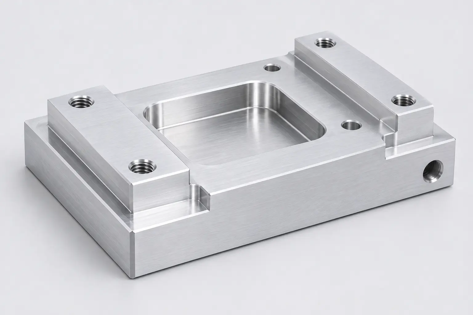 REPRESENTATIVE PART
Drawing-based blocks and mounting bases with machined faces, pockets and hole patterns for industrial assemblies.
Explore this part family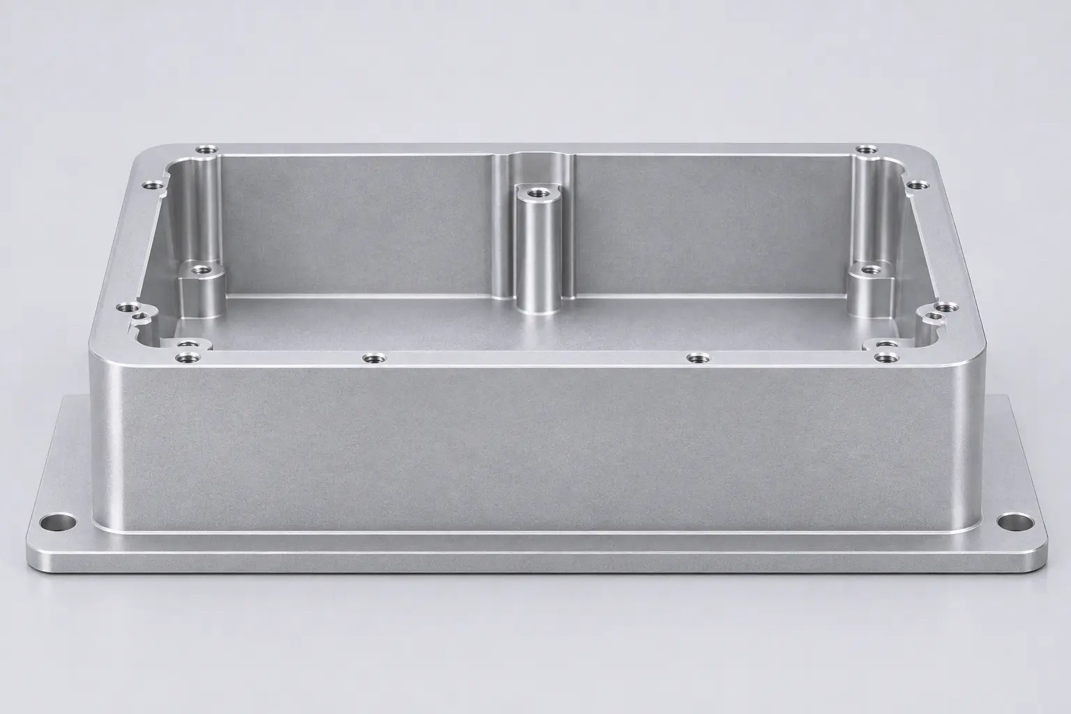 REPRESENTATIVE PART
Machined plates and housing concepts for supporting, locating or enclosing components in industrial equipment.
Explore this part familyA 3D shape alone does not define a production component. Include the requirements that control fit, function and inspection.
Share pockets, slots, internal corners, hole depths and thin-wall features so machining access and setup requirements can be reviewed.
Identify locating faces, mating features and the tolerances that affect assembly. Include the drawing revision and inspection requirements.
Specify the exact material grade, any surface treatment and functional or cosmetic faces. These requirements are confirmed during quotation.
Provide the initial quantity, target delivery and expected repeat demand to support a practical production review.
Part size, geometry, material, tolerances, inspection documents and lead time are reviewed per project. This page does not specify guaranteed machining limits or a universal tolerance.
Our quality approachTell us what the part is made from and how its surfaces must perform. Material availability and any finishing scope are confirmed in the quotation.
Grinding, heat treatment and surface finishing can be coordinated through Belaro's Dongguan and Shenzhen supplier network when they form part of the drawing requirement. Scope and inspection are confirmed per project.
Explore secondary processesFor drawings that require a grinding step after machining, subject to geometry, tolerance and process review.
Coordinated to the material condition, hardness or treatment specification stated in your requirements.
Reviewed against the finish specification, masking needs, functional surfaces and post-finish dimensions.
Send a dimensioned PDF, a 3D model if available, material grade, quantity and target delivery.
Clarify critical features, machining feasibility, inspection needs and commercial scope.
Agree the drawing revision, specifications, quantity and delivery arrangements before production.
In 3+2 milling, the rotary axes position the part or tool before each cut and remain stationary while the three linear axes cut the feature. Simultaneous 5-axis milling coordinates linear and rotary motion during cutting. Belaro supports both methods and reviews geometry, tool access, fixturing and critical dimensions to select the route for your part.
A dimensioned PDF drawing and, where available, a STEP model are a useful starting point. Include the revision, material grade, quantity, critical tolerances and target delivery. The RFQ form accepts a single attachment; related files can be packaged in a ZIP.
Yes, enquiries can be reviewed for low-volume OEM batches and repeat orders. Quantity suitability, production arrangements and delivery depend on the part and the agreed requirements.
Share the required tolerances and datums on your drawing. Feasibility depends on the feature, geometry, material, setup and inspection conditions. Final tolerances must be confirmed during quotation.
List the exact material grade and any finish or treatment specification in your enquiry. Availability, process suitability, documentation and the scope of supply are confirmed per project.
Send the complete drawing and describe the critical interfaces. Select “Not sure — please review” in the RFQ form if the required process is unclear. Any combined process route must be reviewed before quotation.
Share the component, material and batch requirements. Start a focused conversation about your milling project.